(Work-in-progress post! Further info and images coming soon!)
This guide will detail the steps involved in modifying a Blaupunkt IS 70-33 VT television for use with
GroovyUME in order to make the most of the world of native 15kHz video emulation using a real CRT display in conjunction with a PC to play arcade and consoles games. This post is intended to retrace the steps involved setting up my Blaupunkt IS 70-33 VTN as detailed
here and
here.
The completed modification will include externalization of the image control potentiometers and also upgrading the Philips tube found in the Blaupunkt with a newer tube from a Loewe CT 1170 television. Once complete, this TV will feature a formidable combination of an analog chassis and a high-grade, Black Matrix tube.
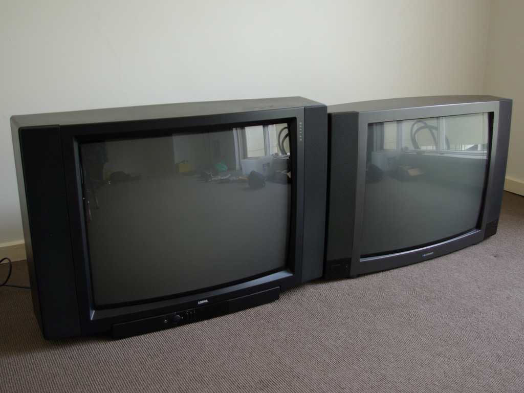
 |
| Loewe and Blaupunkt |
 |
| Blaupunkt (top) and Loewe (bottom) |
Back story:
The Loewe CT 1170 is a fantastic television. The case is made from heavy plastic, the tubes look fantastic and the
E3000 chassis provides a particularly sharp and stable image. The only problem is that this digital chassis type is fairly inflexible when it comes to the wide variety of video modes that GroovyUME outputs. For a start, the E3000 seems incapable of displaying more that 224 vertical lines in NTSC mode (e.g. at 60 Hz). This limitation is fine for many popular arcade games (e.g. CPS1/2/3 and Neo Geo) but games that use 240 or 256 vertical lines get cropped. This is a serious downer if you want to play Irem games or Mortal Kombat.
Also, image adjustment on the E3000 is via a Service Menu. There are a lot of options that can be tweaked in order to get the image just right but it's a slow process. If you want to play games with the screen properly filled and with perfect geometry, you'll soon grow tired of getting in and out of the E3000 Service Menu between video modes.
The benefit of using the Grundig CUC 5360 analog chassis (as used in the Blaupunkt featured) is the greater compatibility between video modes and the ability to quickly tweak the image size using
analog pots. Adjusting the sizing and position using a knob you can physically grab is many magnitudes faster than navigating an OSD driven Service Menu. The effect is instantaneous and it's a very gratifying feeling to see games fill the screen every time rather than putting up with black borders or missing pixels.
.jpg) |
| Loewe CT 1170 (chassis type E3000) |
.jpg) |
| Blaupunkt IS 70-33 VT (chassis type FM 310.32) |
Preparations the donor tube:
The first step in this operation is to remove the tube from the CT 1170. To do this, we first take the back case off:
.jpg) |
| Rear |
.jpg) |
| Back panel removed |
Before going any further, I like to clean out all the dust and grime out using an air compressor. TVs accumulate layers of dust over the years and it's like to get that out of the way before commencing work. It makes the whole process much more enjoyable...
Next, we're ready to start disconnecting the chassis. There are a few connections to sort out before we start removing the yoke.
- Disconnect the left and right speaker cables (coil these up neatly).
- Disconnect the degauss cable and roll it up.
- Disconnect the dag wire from the tube earthing (this green wire runs from the neckboard).
- Remove the neckboard by gently pulling the socket away from the neck.
- Disconnect the anode using a discharge tool (CAUTION! This is dangerous!)
Now we're ready to start removing the yoke. The first step is to loosen the neck clamp using an allen key:
.jpg) |
| Yoke clamp closed |
.jpg) |
| Yoke clamp open |
Next, using a sharp cutting knife, we need to carefully slice through the silicon glue that holds each of the yoke feet in place. Make sure that all movements are controlled so as not to accidentally damage the yoke windings:
.jpg) |
| Slice the silicon under each foot |
.jpg) |
| Yoke cut free from the tube |
With the neck clamp loosened and the silicon blobs severed, the yoke will now slide off the neck. Be very careful not to damage the neck during this process! If the shaft of the neck cracks, the tube will be ruined! However, there shouldn't be any problem if care is taken:
.jpg) |
| Yoke removed from the neck |
Now the entire chassis can be removed from the plastic housing. Undo the screws that fasten the main PCB board into the case. Then, disconnect the cables that connect the chassis to the front panel PCB at the front of the TV case (this PCB holds the function buttons and power switch). Once these are disconnected, the chassis will slide right out:
.jpg) |
| E3000 chassis removed |
.jpg) |
| TV with chassis removed |
Now, the tube can be removed. To do this, lay the TV face down first:
.jpg) |
| Loewe CT 1170 face down |
Then, undo each of the four screws that hold the tube to the TV casing using a 1/8" socket:
 |
| Undo each of the 4 screws |
Once the screws are removed, the tube can be lifted out. With an A66EAK Philips tube, lifting the tube without the help of another person is awkward but it can be done if care is taken:
.jpg) |
| Tube removed |
Once the tube is out, remove the degauss cable, ground strap and plastic braces. Then, the back of the tube can be dusted with a cloth and the screen can polished. Once completed, the donor tube is ready for action!
.jpg) |
| Cables removed, tube cleaned |
.jpg) |
| Philips A66EAK071X11 tube |
Preparing the recipient:
Next, our attention turns to the Blaupunkt. Remove the back cover and clean thoroughly with an air gun:
.jpg) |
| Blaupunkt (back cover) |
.jpg) |
| Blaupunkt (back cover removed) |
.jpg) |
| Dusty chassis |
Take note of how all the cables are folded in place. It's best to take photos for future reference:
.jpg) |
| Chassis and neckboard ground wires |
.jpg) |
| Control cable |
.jpg) |
| Degauss cable (black and grey) |
.jpg) |
| AC input (blue and brown |
Now, disconnect the chassis, ready for removal:
- Disconnect the chassis ground from the tube (white wire).
- Disconnect the neckboard dag wire (black wire).
- Disconnect the control cable (green ribbon cable).
- Disconnect the left and right speaker cables (grey ribbon cables).
- Disconnect the AC input (blue and brown cable).
- Disconnect the degauss coil (black and grey cable).
- Disconnect the headphone, infrared and LED cables (thin green ribbon cables).
- Discharge and disconnect the anode (again, DANGEROUS!)
Now, remove the yoke by repeating the steps shown for the Loewe:
- Remove the neckboard.
- Loosen the tube clamp.
- Slice the silicon blobs.
- Slide the yoke off carefully.
Loosen the two screws holding the chassis in position and slowly slide it out:
.jpg) |
| Blaupunkt chassis removed from case |
Now, lay the TV face down and remove the tube, following the sames steps as the Loewe:
.jpg) |
| Tubes before swapping the degauss coil |
Put the two tubes beside each other and exchange all the components from one to the other:
- Remove the degauss cable (be careful to maintain the shape though).
- Remove the plastic straps (white coloured).
- Remove the ground strap (usually held in plastic with an elastic band and spring).
- Transfer the black plastic clips from the old tube to the next (match up the same positions).
- Place the ground strap onto the new tube.
- Place the middle straps onto the new tube.
- Insert the degauss coil back into the correct position (using the plastic clips).
.jpg) |
| Tubes after swapping the degauss coil and earth strap |
The donor tube is now ready for use with the Blaupunkt chassis!
Drilling holes for the pots:
While the tube is out of the TV case, it's time to drill holes for the 6 potentiometers. To aid in this, cut out a two template to align the holes:
.jpg) |
| Drilling templates |
.jpg) |
| Holes marked out |
.jpg) |
| Paper template aligns with plastic struts |
Next, say a little prayer and drill the holes! For the cleanest results, use a brad point drill bit. For the Vishay pots used in this project, a 10mm drill bit is required. In this instance, the holes I drilled turned out very clean indeed:
.jpg) |
| Holes drilled with template in position |
.jpg) |
| Template removed |
Removing the trimpots:
Next, the original trimpots need to be removed from the chassis PCB. The following chart shows which pots are will be replaced:
 |
| Potentiometer values and Vishay part numbers |
These can be desoldered using some solder wick:
.jpg) |
| PCB with trimpots removed (bottom view) |
.jpg) |
| PCB with trimpots removed (top view) |
 |
| Original trimpots removed from the PCB |
A nice touch is to clean the surrounding area with some circuit board cleaner and a soft bristle toothbrush. This will remove any flux and grime making the holes cleaner and nicer to work with.
Preparing the external pots:
Cut six patch cables to 1 m lengths:
.jpg) |
| Six patch cables |
Next, cut some lengths of heat shrink:
- Cut 18 piece of 1.5 mm tube to 10 mm lengths (ideally, 3 colors).
- Cut 12 pieces of 6 mm tube to 13 mm lengths.
- Cut 12 pieces of 1.5 mm diameter tube to 20 mm lengths.
 |
| Heatshrink selection |
Prepare each patch cable as follows:
- Strip the outer insulation 25 mm from each end.
- Twist the half the shielding together. Cut the other half off.
- Tin the shielding with solder.
- Strip the 2 conductors wires 5 mm from the ends.
- Tin both conductors.
- Heat shrink a 13 mm length of heat shrink over the twisted ground wire.
- Heat shrink one of the 15mm over the point where the insulation was removed (allow 5 mm overlap).
 |
| Cable preparation |
Prepare the pots:
- Tin the 3 solder lugs on the pots.
- Place 3 lengths of heat shrink over each conductor.
- Solder the conductors in place.
- Apply the heat shrink to each lug.
- Label the outer cable with a fine marker (resistor values and control name).
 |
| Patch cable labels |
 |
| Pot preparation |
Install the pots:
Insert each cable and pot into the correct hole. From left-to-right, the order I chose is as follows:
- Vertical Size (V-Size)
- Vertical Position (V-Pos)
- Horizontal Size (H-Size)
- Horizontal Position (H-Pos)
- Pincushion (Pin)
- Trapezium (Trap)
Once the patch cables have been put into position, slice the nut over the cable end and temporarily fasten the pots in place. Turn all the pots to their minmum value (anti-clockwise). Carefully adjust the rotation of each shaft (from the rear) so that each white dot lines up neatly along the front panel:
.jpg) |
| Pots mounted |
Once satisfied, tighten the nuts properly and apply a blob of hot glue to the back of each pot (and nut) to make sure it remains in place.
Solder the patch cables:
Now it's time to attach the patch cables to the main PCB. Match the labels marked on the cable ends with the numbers on the top of the PCB. Lay the chassis on its side to do this.
Re-assemble the TV:
The operation is now nearing completion! The final step is to re-assemble the TV. The hardest part is carefully placing the tube back into the case without accidentally dropping it on the chassis (which is now attached via the patch cables).
- Lay the TV flat on the floor (screen down) and move the patch cables and chassis safely out of the way.
- Carefully lower the tube back into the frame.
- Screw the tube back into place.
- Sit the TV upright again.
- Re-attach the degauss cable, AC input, IR cable, headphone cable, LED cable, control cable, speaker cables.
- Replace the anode carefully. Make sure the clips are firmly gripping the anode hole.
- Attach the chassis ground wire (white) and neckboard ground (black) to the ground strap on the tube.
Double check that all cables have been re-attached and that they are neat and tidy. Then, screw the chassis back into position.
Now, it's time to fit the yoke by sliding it back onto the neck. Gently push it in close to the tube and level it with the screen as best you can. Tighten the neck clamp lightly, leaving it loose enough to allow rotation. The yoke will need to be positioned more precisely by checking with the actual image on the screen once the TV is powered up.
Now, triple check everything! Go back through the list and make sure everything is securely plugged into the correct place and that no cables are unaccounted for. Serious damage can result if the TV is powered on without a key cable attached!
Once all the connections have been thoroughly checked, the TV can be switched on! With no aerial plugged in, you should see snow. Adjust the picture roughly so that the image fits:
 |
| Rough picture sizing before the yoke is aligned |
Now, plug in a computer using a VGA to SCART cable!
Align the yoke:
- Bring up a test grid at 320 x 240 in Arcade_OSD.
- Adjust the vertical size and position controls so that the top and bottom borders come to the edge of the tube mask.
- Gently rotate the yoke left or right to straighten the top and bottom borders on screen with the tube mask.
- You may have to compromise a little between having the top and bottom perfect.
- Once satisfied, gently tighten the neck clamp until the yoke will no longer rotate.
- Lay the TV flat and apply some hot glue to the yoke feet (between the yoke and tube).
 |
| Yoke aligned using a test grid |
 |
| Looking good! |
Finishing touches:
Now, the back of the TV case can be screwed back on. The operation is almost complete and we're (finally) ready to have some fun!
Testing:
To make sure all the controls are working properly and that there are no other issues, what better way to test than to spark up some games?!
.jpg) |
| Forgotten Worlds (384 × 224p @ 59.629 Hz) |
.jpg) |
| Forgotten Worlds (title) |
.jpg) |
| Forgotten Worlds (game) |
.jpg) |
| Caveman Ninja (256 × 240p @ 58 Hz) |
.jpg) |
| Caveman Ninja (title) |
.jpg) |
| Caveman Ninja (game) |
.jpg) |
| The Simpsons (288 × 224p @ 59.186 Hz) |
.jpg) |
| The Simpsons (title) |
.jpg) |
| The Simpsons (game) |
.jpg) |
| NBA Jam (400 × 256p @ 54.815 Hz) |
.jpg) |
| NBA Jam (title) |
.jpg) |
| NBA Jam (game) |
.jpg) |
| Pang (384 × 240p @ 57.420 Hz) |
.jpg) |
| Pang (title) |
.jpg) |
| Pang (game) |
Manual links:
Blaupunkt IS 70-33 VTN at APITE


.jpg)
.jpg)
.jpg)
.jpg)
.jpg)
.jpg)
.jpg)
.jpg)
.jpg)
.jpg)
.jpg)
.jpg)

.jpg)
.jpg)
.jpg)
.jpg)
.jpg)
.jpg)
.jpg)
.jpg)
.jpg)
.jpg)
.jpg)
.jpg)
.jpg)
.jpg)
.jpg)
.jpg)
.jpg)
.jpg)

.jpg)
.jpg)

.jpg)


.jpg)


.jpg)
.jpg)
.jpg)
.jpg)
.jpg)
.jpg)
.jpg)
.jpg)
.jpg)
.jpg)
.jpg)
.jpg)
.jpg)
.jpg)
.jpg)