The idea was to add 3 external adjustments to a little Blaupunkt with a Grundig CUC 6300 chassis. This TV was small enough to be easily rotated for vertical games. Also, it had the all essential vertical size pot and horizontal centring pot.
The whole operation went well until the very end... as you'll see. I've documented the failed project in case it provides some ideas for others. The patch cable system used in the project was intended to allow for easy disconnection of the internal pots for future servicing.
Chassis side:
- Cut 9 patch cables to a length of 10mm (6 blue, 3 white).
- Make a mark 5mm in from each end.
- Strip the insulation on each end back from the 5mm mark.
- Twist ends and then tin with solder.
- Tin the solder cups of the female 9 pin DSUB connector.
- Attach the wire to the connector in following order:
1 - White, 2 - Blue, 3 - Blue, 4 - White, 5 - Blue, 6 - Blue, 7 - White, 8 - Blue, 9 - Blue - Cut 9 pieces of 1.5mm heat shrink to 10mm lengths (6 blue, 3 white).
- Slide the heat shrink pieces onto each patch lead.
- Push each piece up against the connector.
- Apply heat and shrink the tubing.
- Cut a 30mm length of 8mm diameter heat shrink.
- Slide the heatshrink over all 9 leads and position just after the individual heat shrinks.
- Apply heat to the tubing.
- Place connector into DSUB housing and assemble.
- Place a mark on each white cable 20mm from the end.
- Cut a 10mm length of 3mm diameter heatshrink.
- Pin out the leads with a multimeter.
- Make groups of 3 leads in the following combination: 123, 456, 789.
- Apply heat shrink to bunch each group.
 |
| Heat shrink |
 |
| Patch cables |
 |
| Patch cables bound |
 |
| Housing |
 |
| PCB side complete! |
 |
| Leads grouped |
External pots:
- Cut three 2-conductor patch cables to 55 cm lengths.
- At one end of each cable, mark 45mm.
- At the other end, mark 30mm.
- At the same end, mark 40mm.
- Cut 3 pieces of 5mm diameter heat shrink to 20mm.
- Slide over the end with 2 markings.
- Strip the insulation on each cable from the 30mm mark.
- Twist half the shield wire together and trim the other half.
- Cut 3 pieces of 1.5mm diameter heat shrink to 23mm lengths.
- Tin approximately 10mm of each end of the shields.
- Cover each shield with a 23mm length of tube then shrink.
- Slide the 20mm tube 10mm over the break in the insulation and shrink.
- Mark 5mm on each of the other conductors.
- Strip each and then tin.
- Cut 9 pieces of 1.5mm diameter tube to 10mm lengths.
- Tin the lugs on each pot.
- Place tube on each conductor.
- Solder to the pot.
- Heat shrink each tube.
- Tin the shields on the opposite end.
- Cut 3 pieces of 1.5mm diameter tube to 38mm lengths.
- Apply heat shrink to shield leads.
- Mark each conductor at 5mm.
- Strip and tin.
- Tin the cups on the back of male connector.
 |
| Ready for soldering to pots |
 |
| Pots ready |
 |
| DSUB ends |
- Disconnect the neckboard.
- Disconnect the degauss.
- Disconnect the ground wire from the neckboard.
- Disconnect the anode plug.
- Desolder the yoke connections (take a photo first).
 |
| Yoke connections |
 |
| Stencil |
 |
| Holes! |
 |
| Knobs inserted |
- Cut a 10mm diameter piece of tube to a 50mm length.
- Slide the tube over all 3 patch cables.
- Slide small heat shrink lengths over each conductor.
- Solder the individual conductors to the connector (V-Size, V-Position, H-Size). Ground, red, white.
- Shrink the small tubes.
- Position the large tube and shrink.
- Assemble the DSUB casing.
 |
| Heat shrink positioned |
 |
| Heat shrink complete |
 |
| Male DSUB almost complete |
At this point I stopped documenting my steps in the excitement to get it up and running.
 |
| Pot holes |
 |
| Knobs mounted |
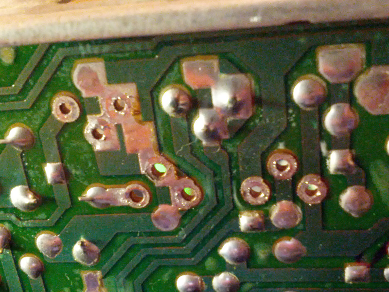
After soldering in the patch cables and connecting the DSBU connector, I fired up the TV. Straight away the vertical size and horizontal position pots worked! However, the vertical position pot didn't work properly. That's where the trouble started... After resoldering, I decided I must have made a mistake with the DSUB assembly so I tried switching the patch wires over for the vertical position pot. BIG MISTAKE! This is what happened next:
 |
| Vertical collapse! |
So, overall, an interesting way to waste 5 or 6 hours. :(
 |
| Trashed! |


